Pin Connection with Node MCU:
- Connect G to a GND port of your NodeMCU
- Connect + to a 3.3v port of your NodeMCU
- Connect S to a digital port on your NodeMCU (in my example port D3)
- Connect L to a digital port on your NodeMCU (in my example port D5)
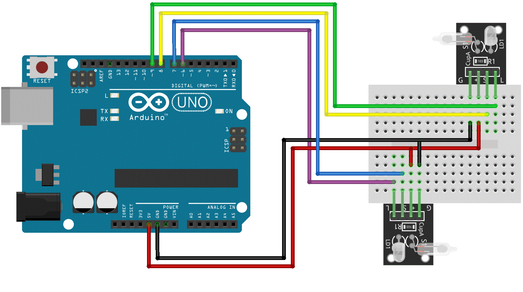
Connection Diagram:

In this Arduino sketch, we’ll use two Switching modules to create the magic light cup effect. The mercury switches in each module provide a digital signal that is used to regulate the brightness of the LEDs using PWM. Tilting the modules will decrease the brightness on one module while increasing it on the other one, creating the illusion of light magically passing from one module to the other.
int ledPinA = 9;
int switchPinA = 8;
int switchStateA = 0;
int ledPinB = 6;
int switchPinB = 7;
int switchStateB = 0;
int brightness   = 0;

void setup()
{
  pinMode(ledPinA, OUTPUT);
  pinMode(ledPinB, OUTPUT);
  pinMode(switchPinA, INPUT);
  pinMode(switchPinB, INPUT);
}

void loop()
{
  switchStateA = digitalRead(switchPinA);
  if (switchStateA == HIGH && brightness != 255)
  {
   brightness ++;
  }
  switchStateB = digitalRead(switchPinB);
  if (switchStateB == HIGH && brightness != 0)
  {
   brightness --;
  }
  analogWrite(ledPinA, brightness);  //  A slow fade out
  analogWrite(ledPinB, 255 - brightness);  // B slow bright up
  delay(20);
}


